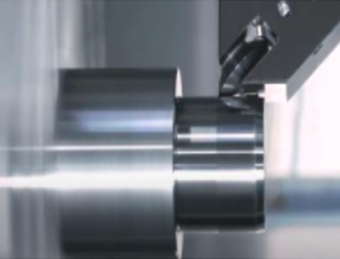
Machining with a lathe has unique challenges.
Inconsistencies in surface roughness
Shortened life for cutting tips
Adding a grinding process with another machine
Superoll™ is the answer.
ROLLER BURNISHING
What is Superoll?
Superoll is a full line of roller burnishing tools that create smoother finishes through compressing the surface - without removing material.LEARN MORE
Explore example case studies
Quality and Precision
These hardened and highly polished tools integrate into machining centers to eliminate secondary processes such as grinding and honing, without removing any material.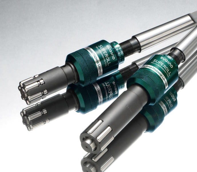
A Mirror-Like Finish
Ideal for processing with shorter cycle times to improve productivity and reduce costs.What is Surface Roughness? How is it Calculated?
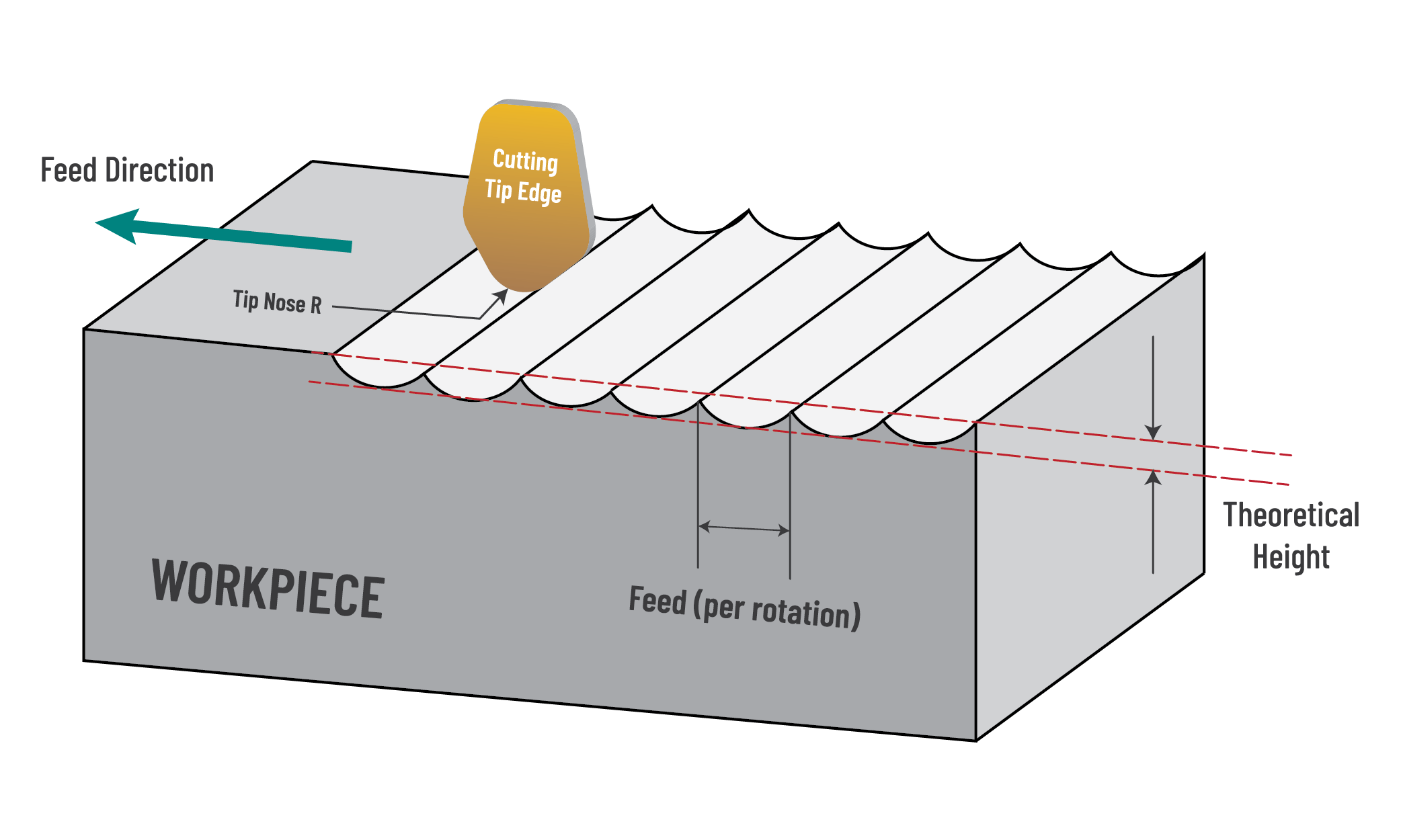
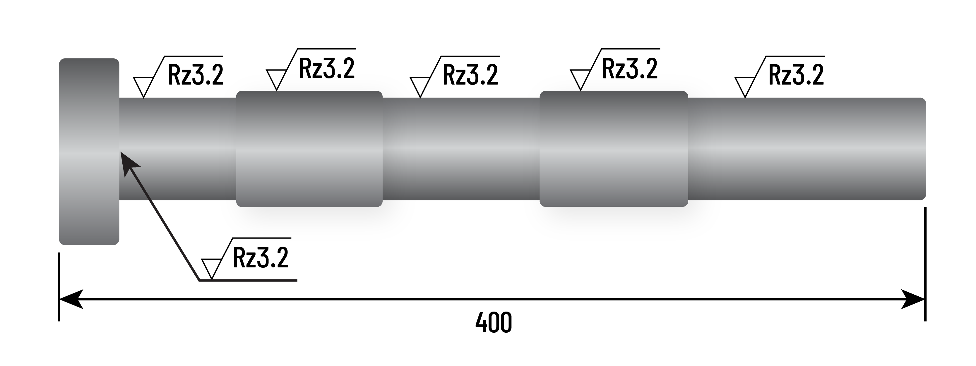
Surface roughness is the geometrical fine irregularities on the surface of an object. In turning, it refers to the height of the peaks and valleys formed by transferring the tip shape of the cutting. Below, you'll find a helpful surface roughness calculator for Lathe turning.
How to calculate theoretical surface roughness [Rz]

F: Feed amount per rotation (mm/rev)
R: Nose R size of cutting tip (mm)

However, does the actual surface roughness match the theoretical roughness in your production site?
Let's explore reasons why they may not match
Why the actual surface roughness does not match the theoretical roughness:
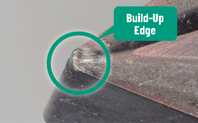
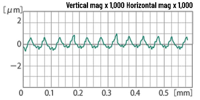
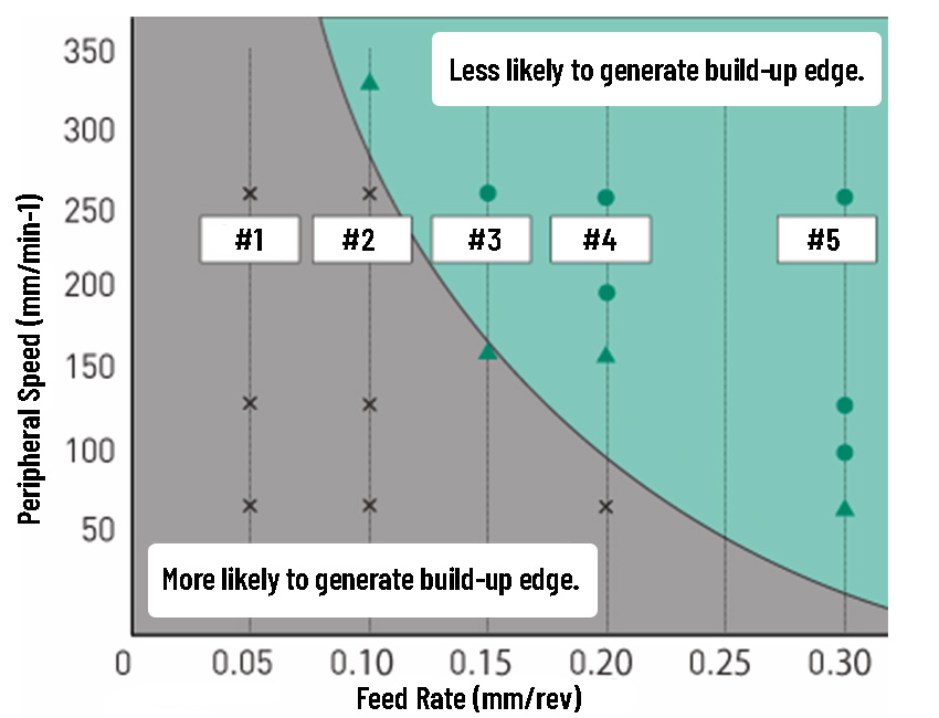
REASON 1: Build-up edge deteriorates the surface roughness.
Machining under inappropriate conditions causes built-up edges at the tip of the cutting tip.
As a result, the machined surface does not have a regular shape, and deviates from the theoretical shape.
Surface property measurement data — machined by
a cutting tip with build-up edge.
Why the actual surface roughness does not match the theoretical roughness:
REASON 1: Build-up edge deteriorates the surface roughness.
Work piece: Φ30 SCM440
Cutting tip: Carbide / Nose R 0.4
Coolant: Not used
Peripheral speed: 50 -250m/min
Feed: 0.05 - 0.3mm/rev
Cutting amount: 0.4mm *Fixed
Why the actual surface roughness does not match the theoretical roughness:
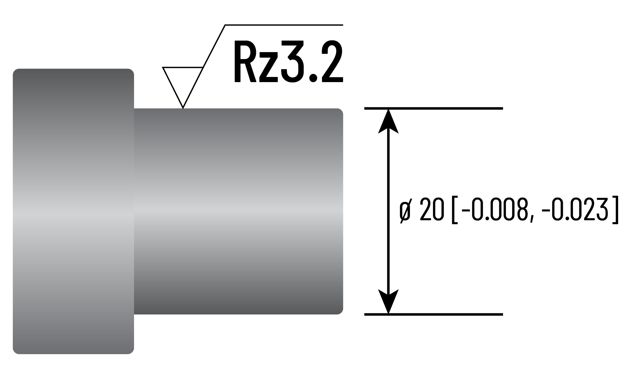
REASON 2: Wear of the cutting tip.
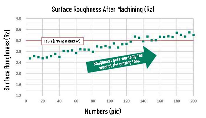
Therefore, when aiming for Rz 3.2 in mass production — assuming that it will gradually deteriorate — appropriate feed rate will be 0.07 mm/rev, and then required peripheral speed will be 450 mm/min (4,775 rpm).
However, if the cutting speed (peripheral speed) is faster, the tool life will be shortened significantly due to the increase in cutting temperature. In addition, slowing the feed rate increases flank wear, which leads to a shorter tool life.
Challenges and Solutions
Explore real-world examples of how Superoll can simplify and improve your process.
Case Example One:
Automate Unstable Works
Problem
The workpiece is too long for high-speed machining. The vibrations at high speed resulted in an uneven finish and surface roughness.
Conventional Way
Achieved dimensional accuracy only by machining at a low speed. But sandpaper hand-finishing was required to meet surface roughness specifications, and uniformity is lacking as hand-finishing varies by worker.
With Superoll
No hazardous waste. The process is fully automated which results in a uniform finish every time. Stable surface roughness. Reduced cycle time.
Case Example Two:
Problem
Problem: The cutting tip life was significantly short due to surface roughness
Conventional Way
The cutting tip needed to be replaced frequently due to the rough surface texture.
With Superoll
Because the Superoll uses compression instead of cutting, the tool life is extended up to four times longer than conventional cutting tips. This saves time and money.
Case Example Three:
Optimizing the Machining Conditions for Crankshafts

Problem
A low rotation speed is needed to maintain balance during the machining process.
Conventional Way
The necessary low rotation speed required a separate grinding step and the purchase of an expensive secondary machine.
With Superoll
Surface stability is achieved without the use of a secondary machine.
Case Example Four:
Integrate the Machining and Grinding Process Together
Problem
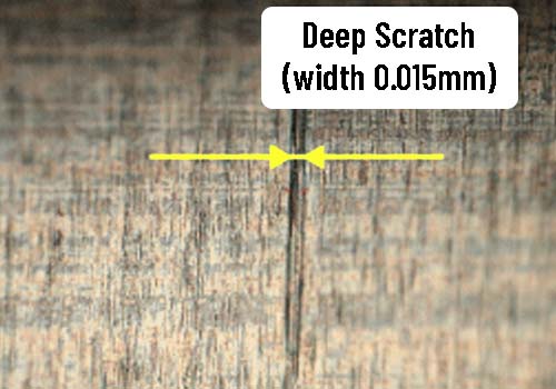
Low speed machining leads to edge buildup. Edge buildup leads to scratches.
Conventional Way
Required visual inspection for all parts.
With Superoll
Allows the machining to be done at high peripheral speed with a fast feed. This creates no edge buildup. No edge buildup = no scratches = no need for inspection. Saving time and labor costs.
Comparing Conventional Methods with Using Superoll in your Lathe
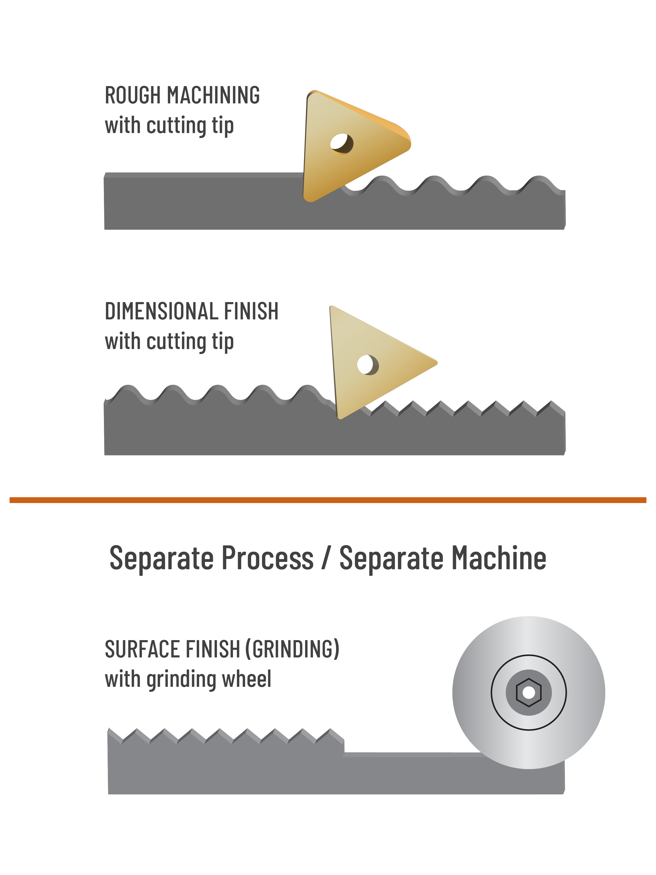
Rough Machining + Dimensional Finish + Surface Finish
Lathe Machining the Conventional Way
The conventional way involves rough machining with a cutting tip first, then dimensional finish. From there, a separate process and machine is often needed to achievee the desired surface finish result.
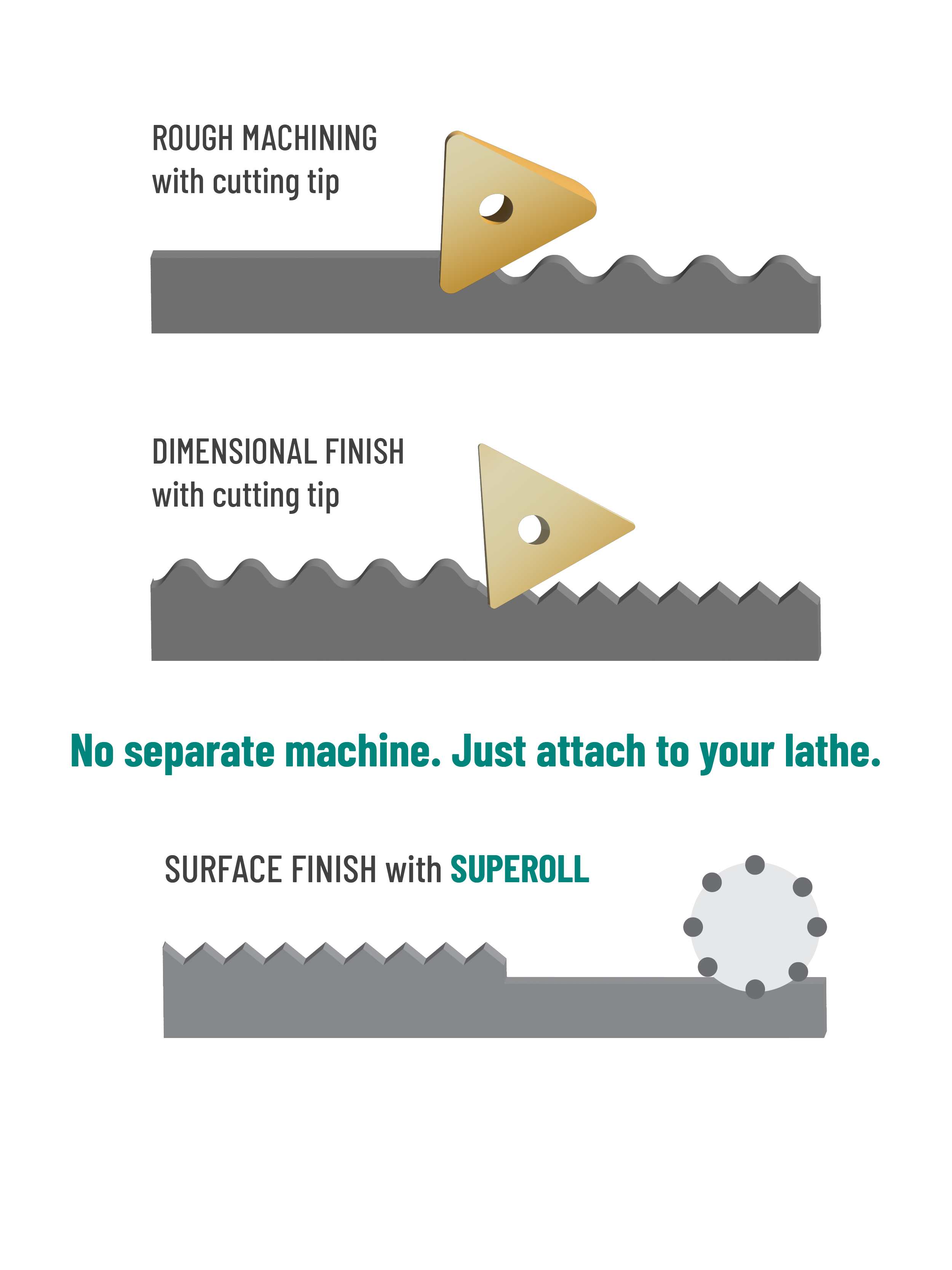
Lathe Machining with Superoll
Using Superoll, you can achieve the precise dimensional accuracy and surface roughness at the same time - and you only need to attach it in your lathe. No separate process needed.
Single Roller Type - Product Lineup
SR5A
For shaft end surface
SR16M
For shaft end surface, taper, R surface
SR5C
For inner
SR16C
For inner
SR3Z
For outer groove side
SR3ZH
For inner groove side
SR24MW
For outer groove bottom
CEZF
For end groove surface
CEZH
For inner groove bottom
Materials
Acceptable Materials
Iron and non-ferrous material, including:
- Stainless
- SCM
- S45C
- FC
- ADC
- Copper
- Brass
Not For
- Titan
- Magnesium
- Wood
- Glass
- Ceramic
- Plastic

Try the Superoll Tool Trial

![Need more guidance? Get help choosing the right tool, discuss a tool trial, or get your questions answered. {{ include_custom_fonts({"DIN Alternate Bold":["Semi Bold"]}) }}](https://no-cache.hubspot.com/cta/default/5001205/interactive-194005608294.png)